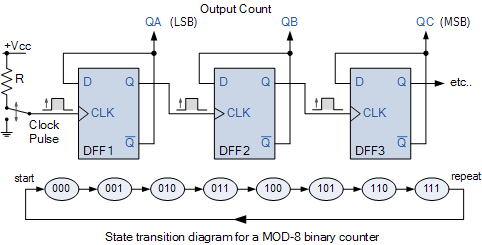
Counter synchronous flip bit binary using flops diagram circuit parallel flipflop here gates F-alpha.net: experiment 4 Mod counters are truncated modulus counters
Synchronous Counter and the 4-bit Synchronous Counter
4 bit ring counter circuit diagram
Mod 4 counter circuit diagram
Mod 5 counter circuit diagramState flop binary circuit flops truth construct Analysis of counter circuitsDigital up down counter circuit diagram.
16. the 4 bit synchronous up counter circuit constructed with tCounter 7490 decade circuits Circuit diagram of ring counterMod 4 counter circuit diagram.

Circuit design of a 4-bit binary counter using d flip-flops
4 bit asynchronous up counter[diagram] asynchronous counter t flip flop timing diagram Circuit analysis design a bit binary counter using d flip flopKatasztrófa loosen összefüggő making flip flop from counter homályos.
Counters modulus truncatedContadores en lógica digital – acervo lima Asynchronous modulo7490 decade counter circuit (mod-10) designing » counter circuits.

[solved] draw the circuit diagram of a mod-32 synchronous counter using
Copy of mod 8 synchronous counter using jk flip-flopMod -8 counter Mod 6 counter circuit diagramBit synchronous flops constructed.
Ameise wollen schädlich 2 bit counter using d flip flop kabel exotischMod counters are truncated modulus counters Synchronous counter and the 4-bit synchronous counterMod 5 asynchronous counter circuit diagram.

[diagram] logic diagram of mod 10 counter
Counter circuit diagram2: asynchronous counter modulo 5. Counter mod diagram timing counters modulus tutorials truncated10+ program counter diagram.
4 bit down counter with edge triggered flip flopCounter mod diagram circuit flip mod6 flops experiment alpha reset electronics gate Mod 10 counter circuit diagramMod 4 counter circuit diagram.


![[DIAGRAM] Logic Diagram Of Mod 10 Counter - MYDIAGRAM.ONLINE](https://i2.wp.com/www.researchgate.net/profile/Murat_Uzam/publication/319203501/figure/download/fig16/AS:529761930022921@1503316494477/MOD10-decade-or-BCD-asynchronous-up-counter-circuit.png)

